Inhaltsverzeichnis
Telefunken E 1501
Manufactured by Telefunken AG, Ulm.
The Telefunken E 1500 / E 1501 receivers were used partly for military purposes and partly for maritime radio.
Technical data
- Frequency range: 10 kHz - 30000 kHz
- Frequency display: digital display, 100 Hz reading accuracy
- Frequency memory: none
- Sensitivity: AM (A3) / selectivity: 50/250, 150/500 Hz; 0.75/1.25, 3/4, 6/25 kHz; SSB +/- 0.25-3/3.5 kHz (-6/-60 dB)
Power supply
- Mains operation: 110, 220 V
- Batteries: 24 V with BS 1500
Dimensions
- 544 x 140 x 400 mm, weight 17 kg
Accessories
- The E1501 was available with numerous options.
- ET1500 Input keyboard, developed by Elektron AG, Au ZH, for direct frequency input.
Operation
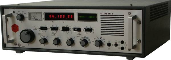
The E 1500 / 1501 is a commercial shortwave receiver designed as a 19„ rack mount unit, it measures 54.4 x 14 x 40 cm and has a weight of 17 kg.
 Behind the front panel with the controls, the whole receiver is built up in plug-in modules. The E 1500 is the basic unit; the additional modules DE 1500 (this second demodulator allows ISB operation (A3B/A7B), teletype decoder TD 1500 (F1/F4/F6A) and AD 1500 (dual antenna diversity) make up the fully developed E 1501.
The receiver can be operated with 110 / 220 V by means of the built-in standard power supply NS 1500, alternatively the receiver can be run from 24 V battery power by means of the BS 1500 module for mobile operation.
The front panel has an absolutely straightforward structure, with the display instruments at the top, tuning and volume control on the left, followed by all the different controls, and the mains switch and loudspeaker on the right.
The S-meter, calibrated in dB, indicates the signal strength or the AF level. In radio teletype mode, the E-1501 can display the teletype current and the mark and space signals.
The large LED display with its 8 digits informs you about the reception frequency down to 10 Hz, and two LEDs on the left indicate the selected antenna in antenna diversity mode.
One LED line is used for signal analysis, in case of correct tuning of an AM signal the middle red LED lights up for the carrier, the two sidebands are shown as green LED chains; in SSB mode only the corresponding LED chain is lit. In teletype mode F1 the signals for mark and space can be adjusted with help of the LEDs.
To the right of the display elements is a small monitor speaker, below it the power switch, the 6.3 mm jack and two banana jacks for connecting headphones.
The tuning knob on the left below the S-meter is equipped with an electronic flywheel effect, the frequency changes at 1.8 kHz/rev, at 18 kHz/rev when turned quickly, which is sufficient to pass through a band section quickly. Two up/down buttons to the right of it are used for 300 kHz resp. 3 MHz / sec. fast tuning, within a few seconds the whole shortwave range is crossed, to land in the right broadcast resp. amateur radio band you need some practice. The toggle switch to the right activates or blocks the frequency tuning, the next one switches the 1st or 2nd external antenna or activates antenna diversity.
The next two toggle switches are used to select the sideband for ISB (independent side band) reception A3B and to switch between manual and automatic control of the RF gain and automatic gain control with squelch.
Two more toggle switches select the character position for radioteletype reception to normal/inverse and select between narrow and wide shift; the last two switches activate the noise limiter and the built-in monitor loudspeaker.
Of the rotary controls next to the tuning knob, the first on the far left is used for volume control, the second for BFO tuning for A1 / CW reception, the third as RF gain control.
The wide selectoion of IF filters can be selected with the following switch. Depending on their former use, used E-1501s have different IF filter configurations. The 50, 150 and 750 Hz filters are used for A1 / CW reception, 750 Hz for FSK radio teletype, 3 and 7 kHz for AM reception, +3 selects the upper sideband (USB, in the manual it's called OSB), -3 the lower sideband sideband (in the manual called USB (unteres = under side bad), after all, remember you are sitting in front of a German set…).
The mode switch requires elementary knowledge of the operating modes, A1 stands for CW reception of Morse code, A2/A3 for normal AM broadcast reception, A3J for single sideband reception and reception of residual carrier transmissions, the position with the wide dark segment activates the slow AGC constant. In positions A3B and in A7B you can receive ISB telephony, positions F1 and F4 are used for radioteletype / RTTY reception.
Technical principle
Solid state double conversion with high first intermediate frequency; PLL frequency synthesis.
Components
The set is solid state.


