
Inhaltsverzeichnis
Ground wave Direction Finder P 100
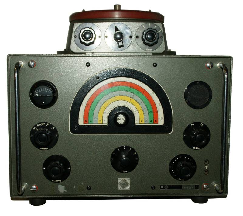
Ground wave direction finder P100, manufactured by Telefunken, Berlin.
The Groundwave Direction Finder P 100 is a transportable battery-operated direction finder that can be used for radio reconnaissance and monitoring, but it is also used for surveys of direction finding sites and was also used in this role in the Swiss Army.

Technical data
- Frequency Range: five SW ranges (1.45 - 2.9 / 2.8 - 5.6 / 5.5 - 11 / 10.8 - 20.5 / 20.3 - 30.5 MHz)
- Frequency display: Analogue dial, reading accuracy 10 - 25 kHz.
- Frequency memory: none
- Sensitivity: AM (A3) 10 μV at 1.5 MHz, 20 μV at 25 MHz for a bearing accuracy of ± 1°, maximum bearing accuracy ± 0.5 °; selectivity > ± 4 kHz.
Power supply
- Mains operation: 110, 220 V
- Batteries: Anode voltage 75 volts (two 75 V anode batteries Daimon 16075, connected in parallel); heater voltage 1.5 V (eight pieces of 1.5 V heater batteries, connected in parallel); grid bias voltage 3 volts (two 1.5 V batteries in series connection as grid biases - 1.5 and - 3 volts).
The batteries are housed in a battery drawer; thanks to a second drawer with fresh batteries, a battery change can be carried out quickly. The set can also be operated outside the cabinet for control measurements using a cable.
Dimensions
- DF receiver: 385 x 425 x 335 mm, weight 18.5 kg
- Frame antenna: 470 x 465 x 40 mm, weight 0.5 kg
- Tripod swivel head: 74 x 145 x 160 mm, weight 1 kg
- Tripod: 970 x 135 x 135 mm ; weight 4 kg
Total system Direction finder on tripod: 3700 x 1100 x 1100 mm, weight 24.5 kg
Accessories
- magnetic compass for aligning the direction finder in north direction

Operation
 The groundwave direction finder can be used as a transportable battery-operated DF receiver within the scope of radio reconnaissance and monitoring, for the localisation of interfering signals and also for surveying direction finding sites before setting up large direction finding systems.
The direction finder is mounted on a wooden tripod. Before use, the set must be aligned to north. For this purpose, the direction finder is equipped with a magnetic compass for northing the direction finder and a sighting device, arranged 90 ° offset to the bearing frame plane.
The direction finder is mounted on the direction finding tripod, the direction finding frame (frame antenna, square single-winding direction finding frame) and the extendable rod antenna of 1.75 m length are mounted on top, the latter serves as receiving antenna for omnidirectional reception and also as auxiliary antenna for side determination.
The set consists of three sub-chassis for the HF stages, the IF stage and parts of the AF stage with an AF filter.
The direction finding module with its controls is mounted on top of the receiver, here you will find the controls for antenna matching, DF sharpening and side determination. The direction finder antenna consisting of a single-winding frame and a rod antenna, which is used as an auxiliary antenna for side detection, are mounted on top.
With the Operation mode switch „Receiver“ on the left side of the front panel, the set can be switched to operation mode A3 regulated (AM - with AGC), A3 (AM, manual RF gain) and A+ (CW, BFO activated). The range switches below the semicircular dial and on the direction finding module select the corresponding shortwave range. The tuning knob in the lower left corner of the front panel is used to tune to the corresponding frequency; when the knob is pulled out, a fine drive is activated.
For operation, first operate the receiver in „AM regulated“ mode and set the sharpening control on the direction finding module to the fourth graduation mark to the left or right. Now the corresponding frequency range is selected (band switch and range control on the direction finding module) and the station is tuned in, the volume is set to loud reproduction of the signal.
 To take a bearing, now set the sharpening control to the 0 mark and set the switch on the DF module to the „taking a bearing“ position. Now turn the bearing receiver by its handles until the bearing minimum becomes clear. Now set the sharpening control to the minimum, turn the direction finder again to the bearing minimum and, if necessary, readjust the sharpening control again to get a maximal the bearing accuracy. The bearing of the station you are looking for can be read on the bearing dial below the receiver; it lies approximately in the direction of bearing or exactly in the opposite direction, offset by 180°.
The side identification must now be made. Switch to side determination with the „Side“ switch on the direction finder, the signal must become audible again. With the addition of a partial signal from the auxiliary or rod antenna, the bearing diagram changes to a cardioid. The direction finder is now turned 25 degrees counterclockwise - in the direction of the decreasing degrees reading on the dial - if the bearing minimum appears at 25 degrees of rotation, the side determination is correct. If the bearing receiver has to be turned clockwise by 25 degrees to reach the bearing minimum, the station is located in the opposite direction to the bearing dial reading. Subtract 180° or add 180° from the reading. Alternatively, you can turn the bearing receiver 180 degrees and repeat the bearing. If the bearing minimum is in „side determination“ mode at a position after turning 25° counterclockwise, the bearing is now correct in the direction, the receiver is facing to.
For acoustic control, headphones can be connected; alternatively, a small monitor loudspeaker is built in.
Technical principle
Single conversion superhet with three tunable HF circuits and a three-stage IF amplifier, A1 with BFO.
The signal is fed from the antennas to the tuned RF preamplifier (V1 - V2, each DF96), tube V3 works simultaneously as 1st oscillator and as mixing stage for conversion to the intermediate frequency of 468 kHz. Two DK96 (V4 - V5) work as IF amplifier stages, the last tube V6 DK96 simultaneously as BFO and mixer / demodulator.
The final tube V7 DL96 resp. 3C4 is also placed on the IF module for technical reasons.
Components
Four DF96 resp. 1AJ4; two DK96 resp. 1AB6; one DL96 resp. 3C4. One calibration crystal QH-1-A (469 kHz).

