Inhaltsverzeichnis
Rohde & Schwarz EK 47
Manufactured by Rohde & Schwarz, Munich.
Jointly distributed with Siemens as E 401
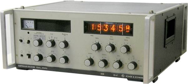
The EK 47 was launched in 1969 as the successor to the venerable EK07. With its digital frequency display with Nixie tubes, which was used for the first time, and its capability to demodulate ISB transmissions, it set new standards.
Technical data
- Frequency range: 10 kHz - 30 MHz
- Frequency display: Digital display, 100 Hz, Nixie tubes
- Frequency memory: none
- Features: Tuning with decadic switches
- Sensitivity: CW to 0.1 μV, SSB < 1 μV, AM (A3) < 5 μV / Selectivity: three filters from the selection 0.15/0.45 kHz; 0.3/1 kHz; 0.6/1.2 kHz; 1/2 kHz; 1.5/4.2 kHz; 6/12 kHz as well as + and - 2.7/3.8 or 3.1/4.3 kHz SSB (-6/-60 dB).
Power supply
- Mains operation: 100 / 120 / 220 / 240 V
Dimensions
- 445 x 195 x 460 mm, weight 30 kg
Accessories
Operation
With its dimensions of 44.5 x 19.5 x 46 cm and a weight of approx. 30 kg, the Rohde & Schwarz EK 47 has turned out to be much more compact than the EK 07. When you lift it by the carrying handles, you are amazed at its weight…
The receiver can be operated from different mains voltages of 110 / 120 and 220 / 240 V.
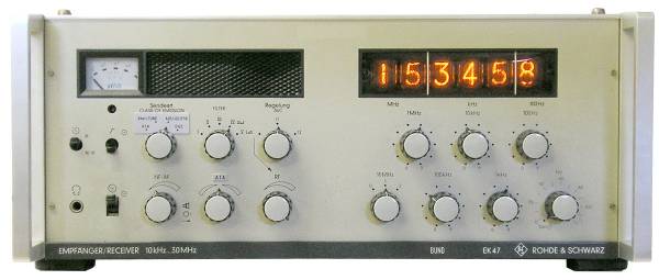
The front panel with the two robust protective brackets has a simple structure:
On the left is the signal strength instrument and the monitor speaker, below them in two rows the most important operating elements: the switch for the measuring instrument, the noise limiter switch, the switch for the operation mode and the switch with the five positions for the IF bandwidths, whereby two positions are reserved for the upper and lower sideband filters for SSB reception. The filter configuration is quite individual, depending on the customer and the purpose for which the set was delivered - before buying a second-hand set, it is worth checking whether the built-in IF filters fit the intended purpose. The third rotary control selects the manual control of the RF gain, the fast and the slow AGC decay time.
Next to the headphone jack and the power switch, you find the rotary controls for the volume, the BFO for CW reception and the RF gain control in the bottom row.
To the right, below the Nixie tube frequency display are the decadic switches for selecting the reception frequency, one knob each for the 10 MHz, 1 MHz, 100 kHz, 10 kHz, 1 KHz and 100 Hz position and a fine control for tuning in between with 10 Hz marks. In the SYN position, the receiver locks exactly on the 100 Hz frequency.
Due to the tuning system with the decadic switches, it is clear that the EK 47 is better suited for use on fixed frequencies than for search reception within a frequency band. However, rapid frequency changes are quite unproblematic - with the EK 07, you sometimes needed more time to crank from one end of a band to the other end.
 On the back of the receiver, you will find the power supply unit on the right, the connections for the antenna (50 Ohm, coaxial) on the left, a 30 KHz - IF output, e.g. to feed an RTTY adapter, an adjustable 600 Ohm - line out - connector and a loudspeaker socket.
After connecting mains and antenna, the operation is straightforward: activate the power switch in the left lower corner, select operation mode (A1 (CW), A3E/J3E (SSB) or A3B (AM)) and IF filter, set AVC for AM mode to fast decay time t1, otherwise to t2, set the frequency with the rotary switches on the right, usually the 10 Hz digit does not have to be tuned, but the receiver can remain in the SYN position and control the volume - if the station can be heard on the frequency.
As a special feature, the IF of 30 kHz can be mixed with the antenna signal in the TUNE position of the operation mode switch; if the tuning is incorrect, a whistling sound is audible; for frequency determination of an unknown station, tuning can then be made to „zero beat“.
If the time and transmitting frequency are correctly selected and the propagation conditions are right, what will be audible with the EK 47 is the desired station in good quality, nothing else - the receiver is highly stable, selective and, as usual with Rohde & Schwarz, the occurrence of mirror frequencies and other „ghost“ signals does not have to be reckoned with: you are sitting in front of a professional receiver.
The receiver is perfectly designed for the reception on fixed frequencies, of course the frequency stability is sufficient for the use of radioteletype converters and CW decoders, for which the use of the fine-tuning may sometimes be necessary. Unfortunately, the number of radio services (press agencies, etc.) transmitting on fixed shortwave frequencies has declined sharply in recent years, so that the range of use for the EK 47 has become narrower; the set is not particularly suitable for search reception on the shortwave bands.
Technical principle
Technically, the signal first passes through a low-pass filter for the VLF range below 150 kHz, otherwise a band-pass filter for the medium-wave frequencies 150 - 1500 kHz or a high-pass filter for shortwaves. An automatically switched preselection with suboctave filters was available as an option.
First, the antenna signal is converted to 73.03 MHz in a ring mixer, this first IF is then converted to the second IF of 30 kHz with the signal of the PLL synthesizer from 73.04 - 103.03 MHz. After an IF amplifier stage and the filter bank, the signal passes to a second IF amplifier, AM is demodulated in a diode demodulator, optionally an ISB demodulator was available. For SSB demodulation, a product detector is used.
Components
The set is solid state.
Technical documentation
- Siemens Radio Receiver E-401, manual part 1 - 3, identical to R&S EK47
- Siemens Radio Receiver E-401, Appendix, circuit diagrams and lists of parts, identical to the R&S EK47.


